Circuit detail
The F-2B was inspired by the Fender Dual Showman amplifier. In the late '60's, we routinely
added preamp output jacks to Dual Showman amplifiers and substituted an external power
amplifier for the built-in quad 6L6's, most usually a MacIntosh 75.
 The F-2B came about to provide the same preamp
functionality in a rack-mounting package, as the Dual Showman was considerably wider than
the standard 19 inch rack. The F-2B came about to provide the same preamp
functionality in a rack-mounting package, as the Dual Showman was considerably wider than
the standard 19 inch rack.
We took the opportunity to make a small
improvement in the input jack circuit, while providing identical functionality. Plugging
into Jack 1 alone gives full sensitivity, while Jack 2 alone is attenuated 6 dB. If signals
are plugged into both jacks simultaneously, mixing resistors combine the signals and give
isolation to the two input sources. In the original circuit, the mixing resistors are
always in series with the grid of the first stage, and contribute a small amount of Johnson
(thermal) noise. Our jacks have additional contacts which completely switch out the mixing
resistors when using Jack 1 and the ultimate quietness of the tube is preserved.
As in its predecessor, the instrument signal is
amplified by the first stage before any volume control. Without the wide dynamic range
provided by the 300 volt supply, the first stage could be easily overloaded by large
transients which are characteristic of electric instruments.
The tone control section follows, with a circuit
attributed to Tom Walker, wherein the Bass and Treble controls contribute mostly boost and
the Mid control provides cut only. While there is no absolutely flat position, the response
is reasonably flat with the controls set at 2 - 10 - 2, with the bright switch off. The
circuit can be described as interacting, such that the frequencies affected by each control
is changed somewhat by the settings of the other controls. Additionally, when all 3 tone
controls are turned to 0 then no signal is passed at all. These effects, while not suitable
for a music reproduction system, have nonetheless proved highly pleasing for electrical
instruments and have been adopted by a wide group of manufacturers.
The Volume control immediately follows the tone
control section. The Bright Switch connects a capacitor around the volume control, the
value of the capacitor being selected to bypass only the high frequencies. The effect of
the Bright Switch is also interactive with the Volume Control, and there is no effect if
the Volume control is turned up to 10, and the magnitude of the effect changes, depending
on the setting of the control.
The signal loss of the passive tone controls and
the volume control is made up by the second stage, also a common-cathode vacuum tube stage.
The second stage plate circuit feeds the output jack. Since the output impedance of the
tube circuit is fairly high, the power amplifier(s) should be located adjacent to the F-2B
so that short connecting cords can be used. While the output circuitry of the F-2B can
satisfactorily interface with the vast majority of power amplifiers, the F-2B does not
work well if the power amplifier input impedance is lower than 10 K Ohms or if the power
amplifier has very low sensitivity.
The mono output on the rear of the F-2B provides
a facility to use a stereo instrument with a mono power amplifier. The mixing resistors
associated with the mono jack are only connected together when a plug is inserted, thus
preserving maximum stereo isolation when using the separate Channel A and Channel B
outputs. Another application is to connect the two channels in cascade, by a cable from the
Channel A output jack on the rear to the Channel B input jack on the front. The power
amplifier is connected to Channel B's output. The signal from Channel A is high enough to
drive the first stage of Channel B into distortion. The tone controls of Channel A are
used to emphasize those frequencies which will be most distorted, while the controls of
Channel B shape the color of the resulting distortion. Channel A's volume control sets
the amount of distortion, while the Volume Control of Channel B sets the output level
(Master Volume).
The power transformer has taps so that the F-2B
can be operated from 100, 120 or 240 volt lines (Mains). It is necessary to open the
cabinet and solder the correct tap to the power switch to make the voltage change, however.
The Line (Mains) input connector is the IEC (computer type) so the power cord is detachable.
The layout of the circuitry and the lead dress to the front-panel components are carefully
planned to reject external hum fields. In addition, an internal hum-balance control rejects
hum from the AC heater supply. The package is a single unit standard EIA rack mount steel
enclosure designed to survive on the road.
| 
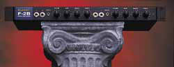 The F-2B
contains two independant preamp/tone control sections.
The amplification is entirely vacuum tube powered. It is normally used as a stereo preamp
to interface stereo instruments to power amplifiers. Jacks are provided on the rear for
outputs from each channel. In addition a Mono output jack is provided which combines both
channels when the F-2B is used with a Mono power amplifier
The F-2B
contains two independant preamp/tone control sections.
The amplification is entirely vacuum tube powered. It is normally used as a stereo preamp
to interface stereo instruments to power amplifiers. Jacks are provided on the rear for
outputs from each channel. In addition a Mono output jack is provided which combines both
channels when the F-2B is used with a Mono power amplifier